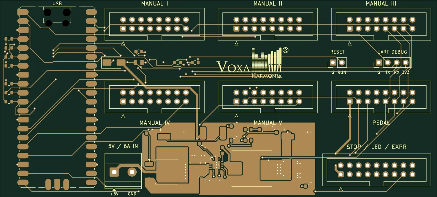
Central control
Ctrl Module
The updated central ModSystem controller brings together five manuals, a pedalboard and the stop/LED/expression module, communicating with the computer through the Pico USB connection.
Details
Kőszegi-Szabó József

21 modules for central control, key sensing, stops and LED feedback. Choose the solution for your instrument and request a quotation.
MODSYSTEM / HYBRID ORGAN
From the console to real pipe magnets: the Driver controller, isolated Gateway and local power boards have distinct roles. The six new modules are in development; complete system firmware and physical validation remain to be finalised.
Ctrl Module Driver → Organ Bus Gateway → isolated RS-485 branch → Magnet / Stop / Slider / Motor nodes. Each power bank needs a local, separately fused DC supply.
Hall Velocity 1/8/12 → 88 Velocity Base (Pico 2) → USB-MIDI → computer. Separate 5 V/2 A adapter; star-wired 3.3 V Hall-board supplies, separate from signal headers.
Every PCB-mounted component, including separately procured ICs, MOSFETs, Pico modules, capacitors and connectors, with assembly. External magnets, motors, supplies, braking resistors, cooling, mechanics and installation are separate peripherals. Development-module prices are planned and availability must be confirmed.
ModSystem → Central control
The updated central ModSystem controller brings together five manuals, a pedalboard and the stop/LED/expression module, communicating with the computer through the Pico USB connection.
Details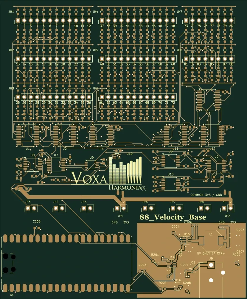
88-key velocity system
Standalone Pico 2 USB-MIDI piano controller for up to 88 analogue Hall signals. Hall Velocity 1/8/12 boards connect directly; no separate Ctrl Module is required.
Details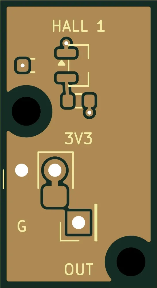
88-key velocity system
A board with 1 analogue Hall sensor for magnetic key-motion sensing. Outputs connect to the analogue inputs of 88 Velocity Base.
Details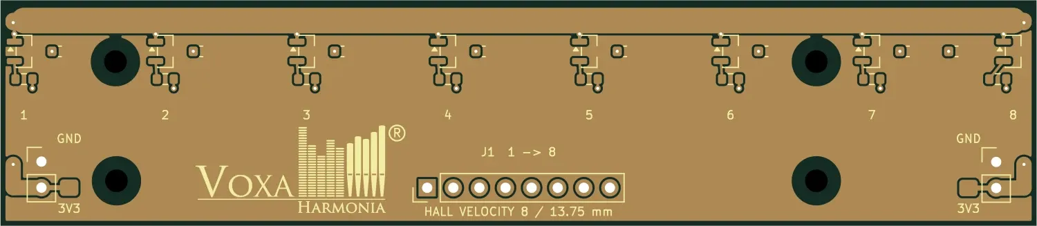
88-key velocity system
A board with 8 analogue Hall sensors for magnetic key-motion sensing. Outputs connect to the analogue inputs of 88 Velocity Base.
Details
88-key velocity system
A board with 12 analogue Hall sensors for magnetic key-motion sensing. Outputs connect to the analogue inputs of 88 Velocity Base.
Details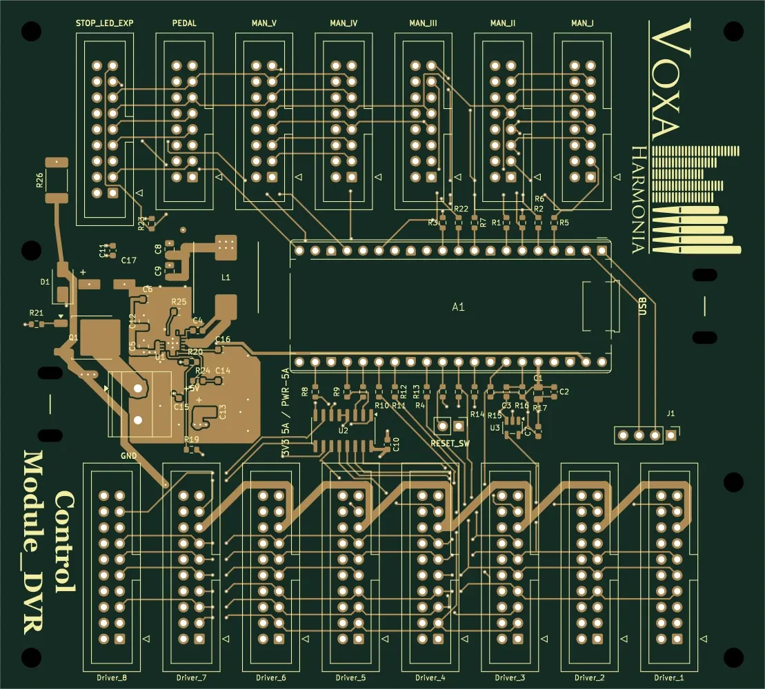
Central control
The central ModSystem controller built around a Raspberry Pi Pico. It connects manuals, a pedalboard and the stop module, with separate driver-bus connections.
Details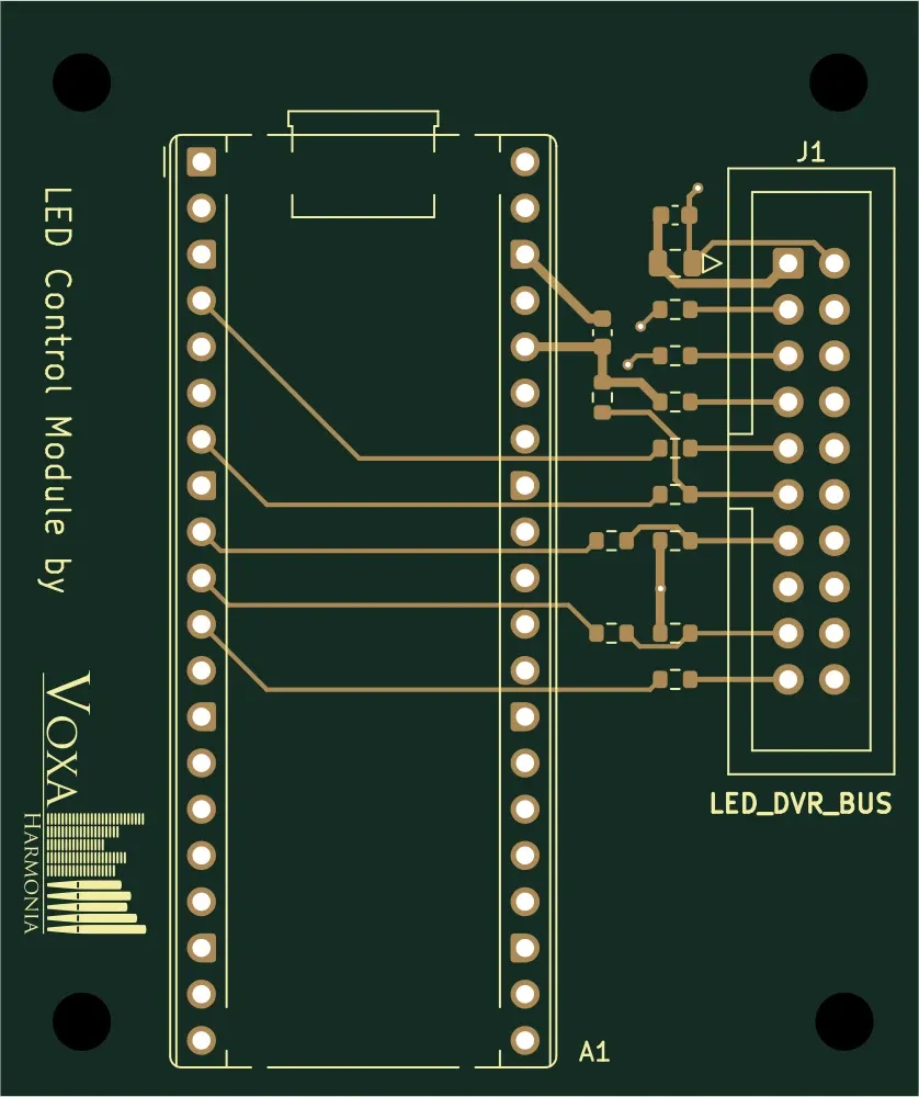
LED control
A dedicated USB-MIDI controller for daisy-chained LED Driver 64 boards. It converts computer MIDI messages into LED-driver control signals.
Details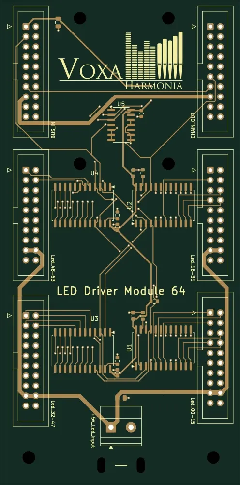
LED driving
A driver board for 64 individual LED channels, using four TLC5925 constant-current ICs. BUS_IN and CHAIN_OUT allow daisy-chaining to further boards.
Details
Keyboard – digital Hall
A manual board for 64 individual digital Hall sensors. Magnetic key sensing provides contactless on/off states to the central controller.
Details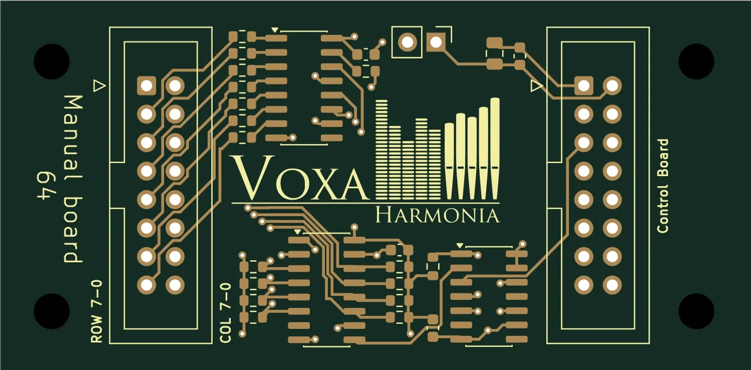
Keyboard – switch matrix
A manual board that reads an 8×8 switch matrix for reed-switch or other suitable contact keyboards. The matrix accepts 64 switching points.
Details
Keyboard – analogue Hall
A board sampling 64 analogue Hall inputs to track key movement. Central-controller firmware can derive key velocity from the 12-bit ADC’s raw samples.
Details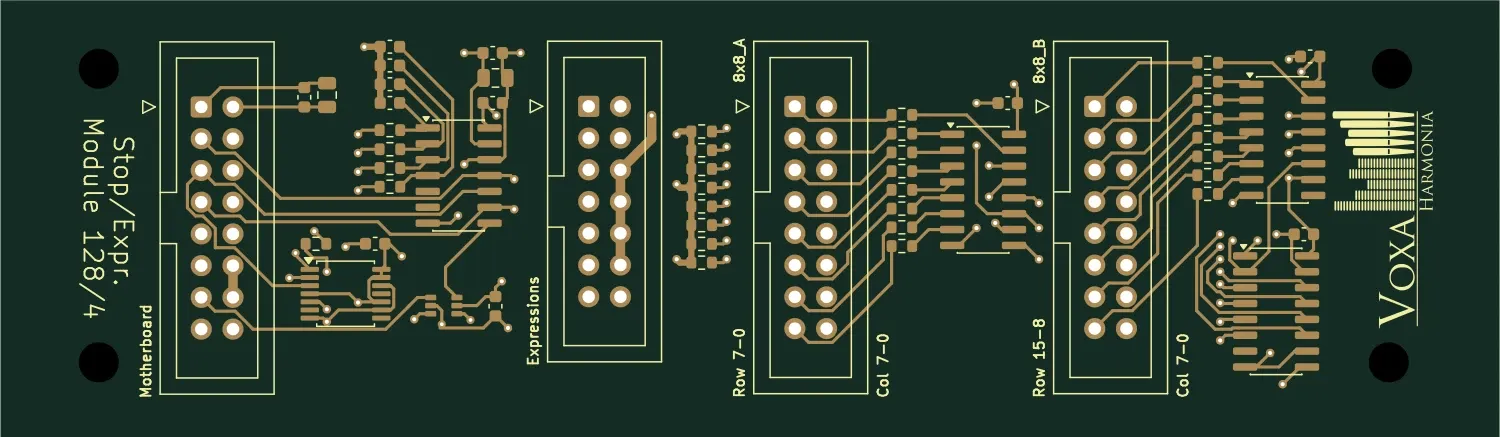
Stops and expression
A module for stop switches and four analogue expression controls. It forwards switch-matrix and pedal signals to the central controller.
Details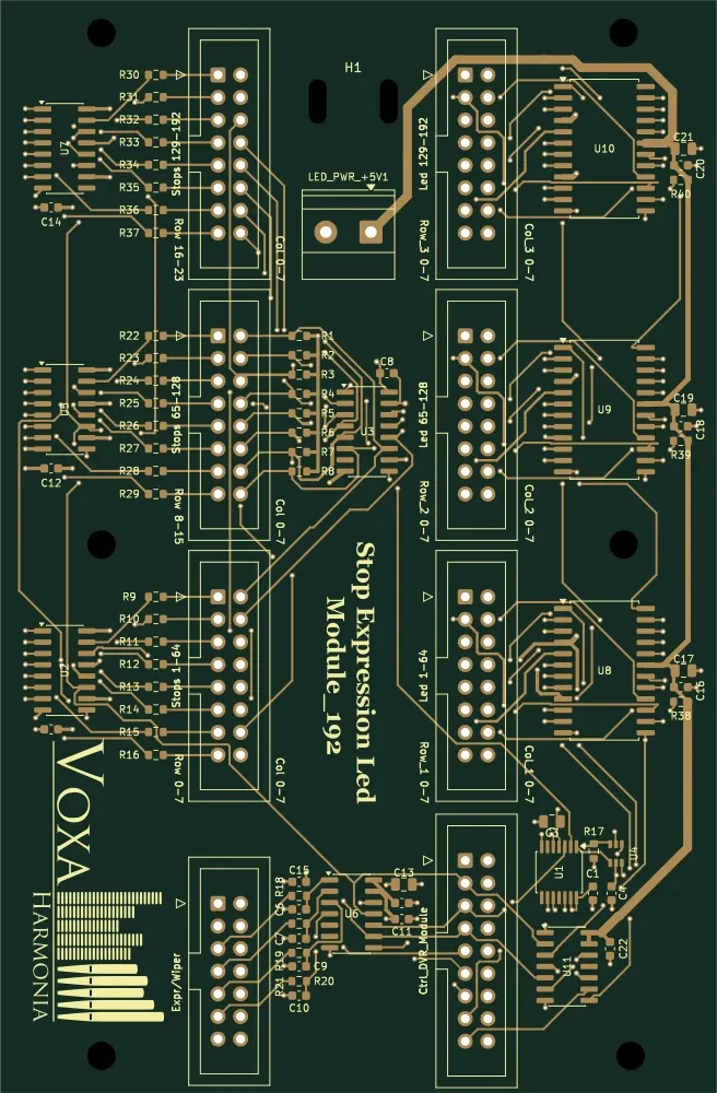
Stops, LEDs and expression
A board combining three 8×8 stop banks, LED feedback and four expression inputs. A single module handles switch scanning and illuminated stop indication.
Details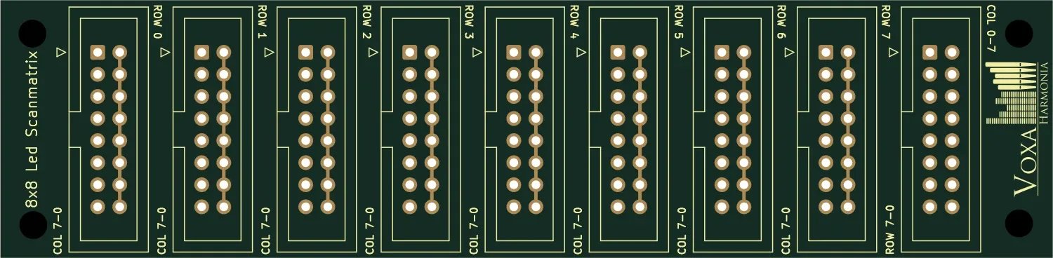
LED-matrix connections
An 8×8 row–column connection board for an LED matrix. IDC connectors provide organised wiring for 64 matrix positions.
Details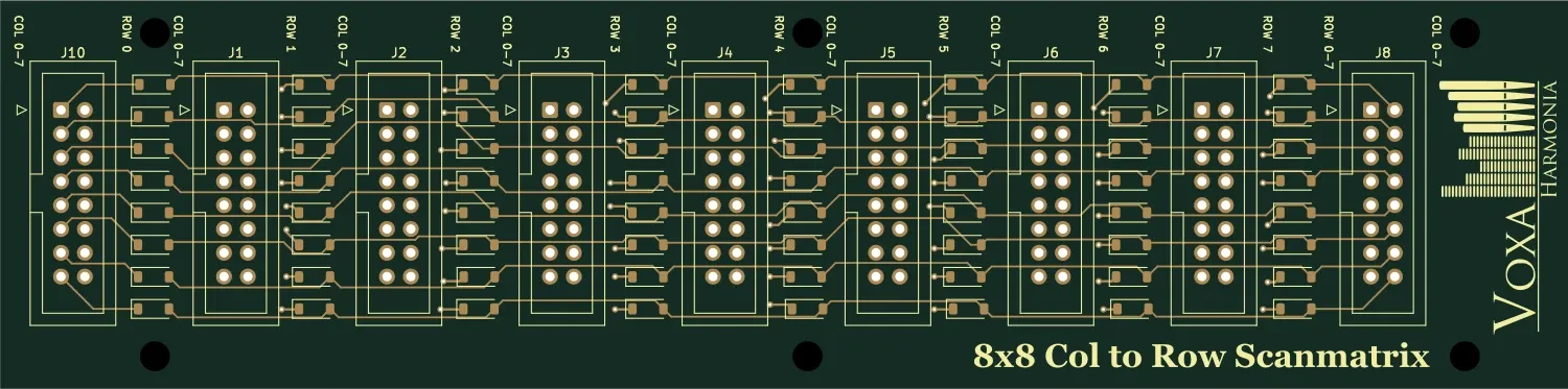
Switch matrix
A Col-to-Row matrix board organising 64 switching points. Individual 1N4148W diodes provide isolation within the switch network.
Details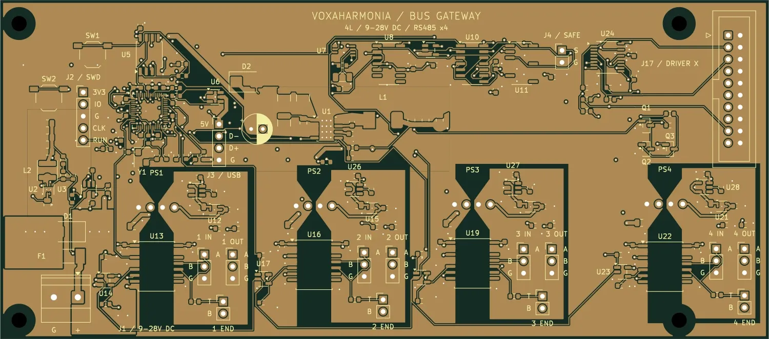
Hybrid organ · power control
In development · planned board
Gateway between the ModSystem Driver controller and four galvanically isolated RS-485 field-bus branches. One gateway can serve multiple daisy-chained magnet and actuator boards.
Details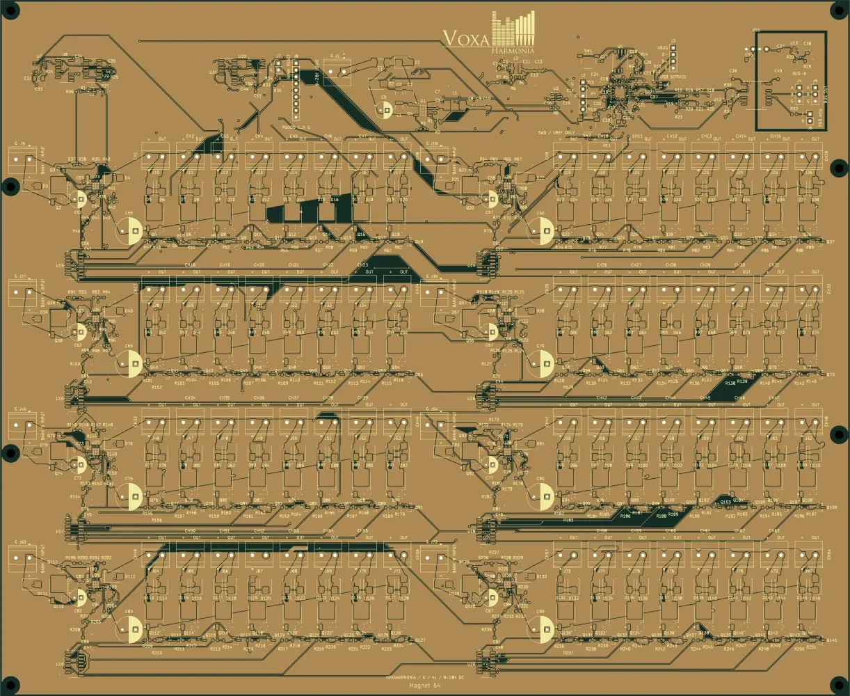
Hybrid organ · power control
In development · planned board
64 independent low-side outputs for common-positive DC note magnets. Designed for smaller electro-pneumatic note magnets.
Details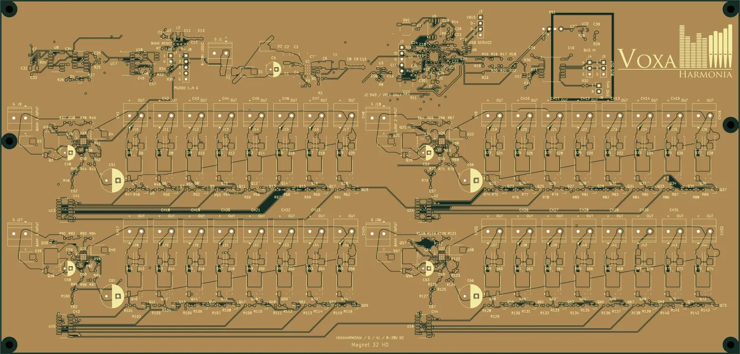
Hybrid organ · power control
In development · planned board
32 independent low-side outputs for common-positive DC note magnets. HD version for higher-current coils.
Details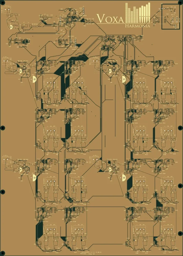
Hybrid organ · power control
In development · planned board
Node designed to control 16 dual-coil stop-action magnets with ON/OFF pulses. Drawknob mechanics are separate peripherals.
Details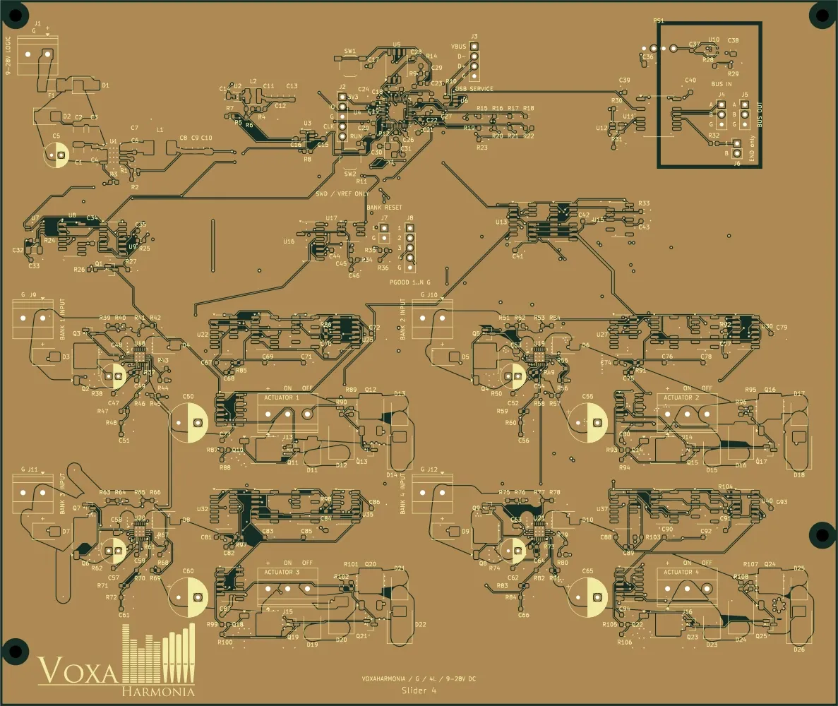
Hybrid organ · power control
In development · planned board
Power node designed for pulse control of four larger dual-coil stop or slider actuators, with individual bank protection and a defined thermal envelope.
Details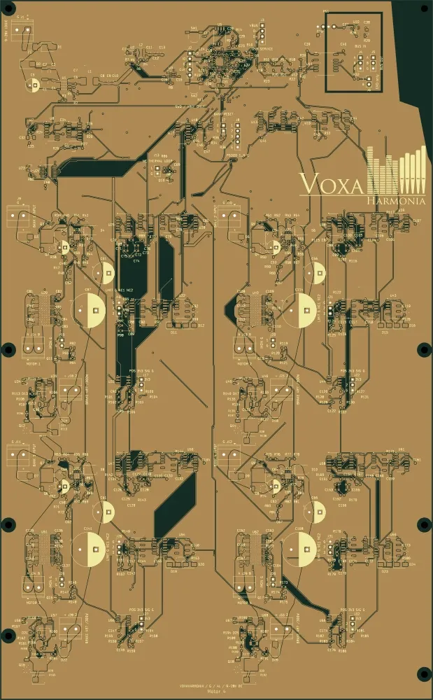
Hybrid organ · power control
In development · planned board
Node designed for four bidirectional DC motors driving swell shutters or other organ actuators, with provisions for limit and position feedback.
DetailsMODSYSTEM / DRIVER BUS
Manual and pedal signals reach the central controller. USB–MIDI connects to a virtual instrument; the Driver Bus connects to matched driver modules for the physical organ.
Input modules read the keys and switches.
Control Modul Driver links the console, USB–MIDI and driver ports.
Ctrl Module Driver → Organ Bus Gateway → isolated RS-485 branch → Magnet / Stop / Slider / Motor nodes. Each power bank needs a local, separately fused DC supply.
Ctrl Module Driver → Organ Bus Gateway → isolated RS-485 branch → Magnet / Stop / Slider / Motor nodes. Each power bank needs a local, separately fused DC supply. From the console to real pipe magnets: the Driver controller, isolated Gateway and local power boards have distinct roles. The six new modules are in development; complete system firmware and physical validation remain to be finalised.

Manuals, pedalboard, stop switches and expression controls each connect through the appropriate input module.

The separate USB–MIDI LED system can provide 192 or 256 LED channels using 3 or 4 daisy-chained LED Driver 64 modules, with firmware configured for the module count.

Illustrative system diagrams. Hybrid driver modules, firmware, protection and power supplies are specified for each project. LED Driver 64 drives LEDs; it is not a magnet driver.